 |
Fundamental Technologies
Voyager LECP Pages
|
Voyager LECP Data Analysis Handbook
List of Figures
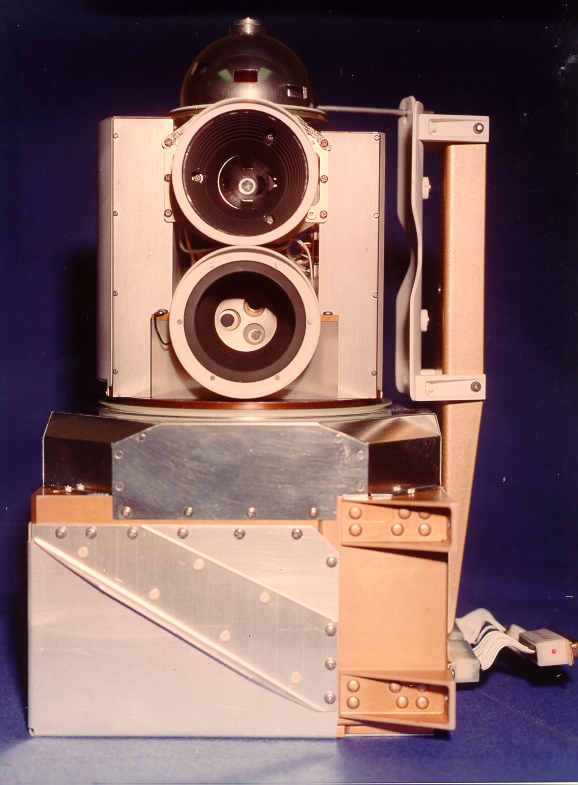
Instrument and Investigation Descriptions and Images
Engineering Design
- Detector Tests at Teledyne-Isotopes Using the Pioneer F-08 RTG:
- Figure 1. Counting rate vs. distance, 100 micron detector
- Figure 2. Rough energy spectrum obtained at a distance of 26 cm
- Figure 3. Same as figure 1, for 200 micron detector
- Figure 4. Differential and integral energy spectrum for 200 micron detector
- Figure 5. Differential and integral energy spectrum for 100 micron detector
- Charged Particle Telescope diagram
- High Intensity Detector System for the Study of the Magnetospheres of Outer Planets:
Data File Descriptions
Calibrations and Channel Definitions
- Delta Detector Characteristics
- LEPT Logic and PHA Design
- Time Constants for V1 LECP
- The Voyager LECP Pulse Height Analyzer (PHA)
- Specification - LECP Pulse Height Analyzer
- Rate Tests
- Random Pulser Test
Instrument Modeling Reports
- An Analysis of the Performance of the Magnetic Deflection System in the Voyager
Low Energy Charged Particle Experiment (S. Shodhan master's thesis)
- LEMPA Aperture Notes and Drawings
In-Flight Calibration Studies
- Study of Voyager 2 LECP Responses in Partial Exposure ("Chicken") Mode
Analyzed Observations
Saturn Operations
Return to Voyager LECP Data Analysis Handbook Table of Contents.
Return to Fundamental Technologies Home Page.
Last modified 8/26/05, Tizby Hunt-Ward
tizby@ftecs.com