| |
Fundamental TechnologiesVoyager LECP Pages |
Figure 4.3. Projection of the modelled sensor assembly on the xy plane. The dots indicate the magnetic field pointing into the plane of the paper.
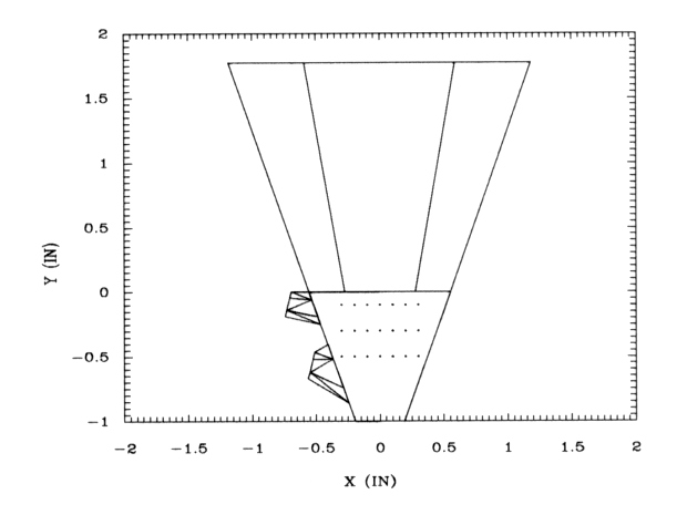
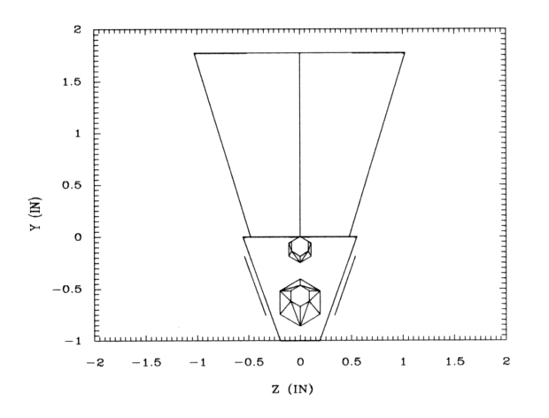
Figure 4.4. Projection of the modelled sensor assembly on the zy plane. The two lines on either side of the assembly show the two tilted magnets.
Return to thesis table of contents.
Return to Voyager LECP Data Analysis Handbook Table of
Contents.
Return to Fundamental Technologies Home Page.
Last modified 12/9/02, Tizby Hunt-Ward
tizby@ftecs.com