
Line 1 of the IVF contains a character string which may name or describe the file (cf., figure 3.3-6.) The next set of lines describes the flux-boxes and have the general form:
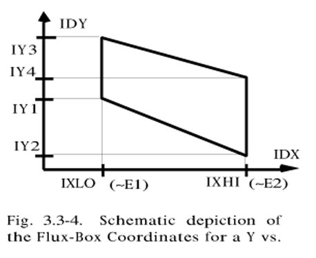
IBXNAM IBNUM, IDY, IDX, IXLO, IXHI, IY(1,i), IY(2,i), IY(3,i), IY(4,i), E1, E2, G, IADDON, INORM,
where each of these names is described in figure 3.3-3. Typically the chemical symbol for the ion is used for IBXNAM, as in figure 3.3-6. The second datum corresponds to the rate-channel to be used in the flux calculation. For CH01 - CH09 it is necessary to indicate which detectors in the D1a, D1b mosaic are to be included; as indicated in figure 3.3-3., this is accomplished via a three digit code, where the first digit is the channel number, the second digit is 0 (zero) and the third is either 0, 1, or 2. For the last digit, a 0 indicates the inclusion of both D1a and D1b events, while 1 or 2 means that only D1a or D1b events, respectively, will be used in the flux determination. The next six data define the coordinates of the corners of the flux box. The two data that follow the coordinates, E1 and E2, define the energy range such that E1 is the energy/nucleon associated with the IXLO channel and E2 is associated with IXHI. The geometric factor, G, is next, followed by two special purpose flag-codes IADDON and INORM. IADDON is used to add up the flux from several boxes. If the flag is equal to 1 in a particular line then the flux from the box defined by the current line is added to the flux of the box associated with the previous line. This can be used to calculate the flux when the particle track crosses a rate-channel boundary or to determine the flux for two adjacent boxes....The INORM code is used to normalize the box to a rate other than the one normally associated with the a box. In this way the box-counts, BXCNT (Cbox ), are associated with the IBNUM valued rate-channel, but the valid PHA counts, VPHCNT (CPHA), the time coverage, RTCOV (∆T), and the rate-counts, RTCNT (Crate), are all associated with the rate-channel with the value INORM.

Below the box specifications in the IVF is a termination flag 0,0,0,0 which signals the beginning of the rate-specification lines; each of these lines have the following form:
IRNUM, RMIN, RMAX, D15(1,j), D15(2,j), D2(1,j), D2(2,j), D3(1,j), D3(2,j), D4(1,j), D4(2,j)
where each data element is described in figure 3.3-5. IRNUM is the rate- channel number -- not the 3-digit code as in the box section (cf. lines 11, 12 and 13, figure 3.3-6.) -- and the limits on the rate take the values defined by RMIN and RMAX. Typically RMIN is set to zero and RMAX is chosen to exclude rate-spikes which are found in the data set. Next are the PHA energy-channel limits. These are set to exclude invalid PHA data which are found to be in error or are not desired for a particular application. For example, if one wants to insure, (beyond the on-board electronic logic circuits), that the ions in question are stopped in D2 after passing through D1, then placing a low upper limit on D3 and D4 would be advisable. The D15 notation is meant to remind us that this PHA coordinate contains data for either D1 or D5 depending on the PHA-ID (see section 1.). Following these data is the final termination flag.